
0
Owner's of the Sea Gull Lighting Fan Sea Gull Lighting Fan gave it a score of 0 out of 5. Here's how the scores stacked up:
15070-UL-ENG
I
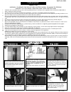
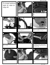
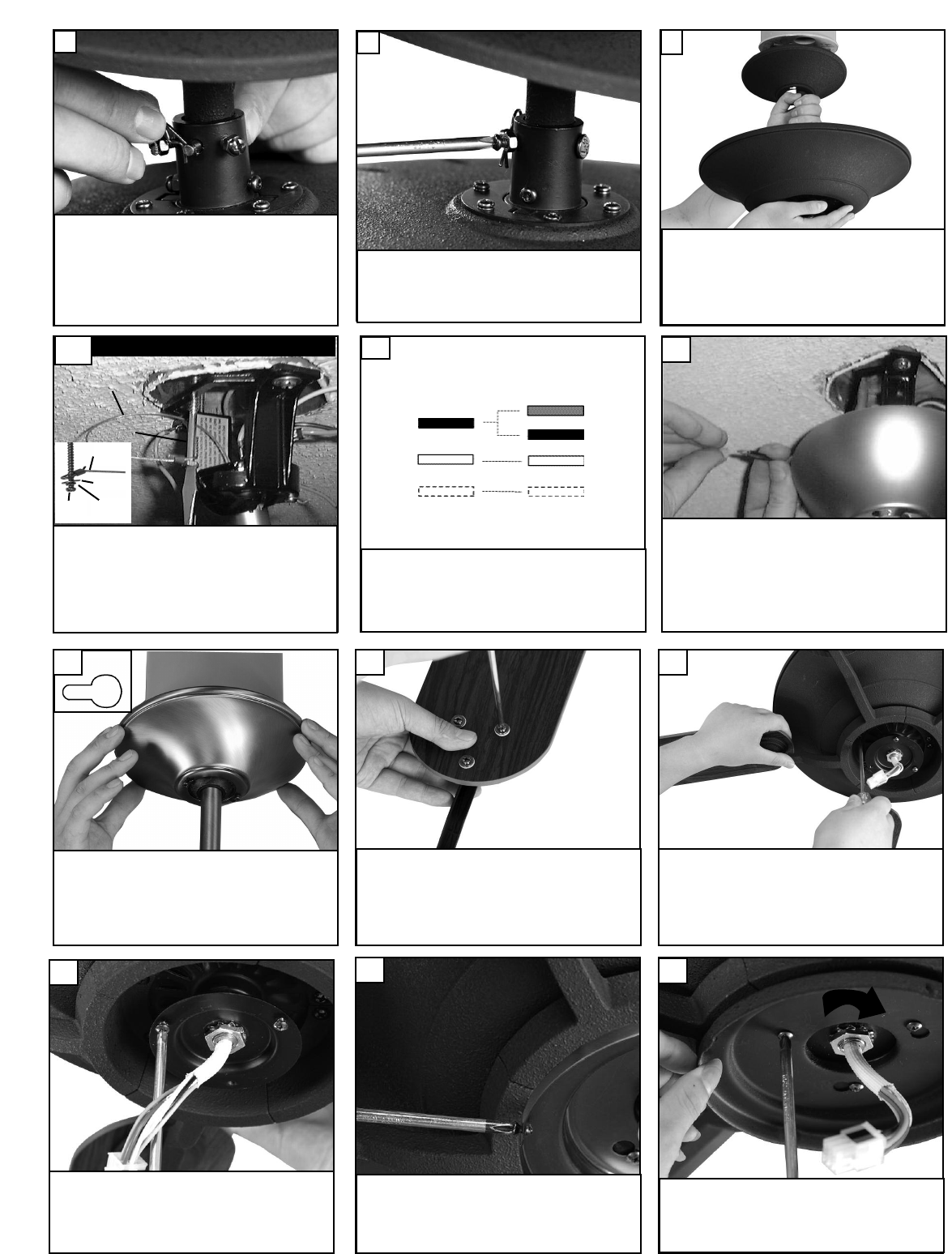
nsert downrod into yoke on top of
fan body. Align the hole in the down-
rod with hole in the yoke. Insert pin
through the yoke and downrod until
t
he point appears on the other side.
Install the keeper.
7
T
ighen set screws and nuts to secure
downrod in yoke.
8
Raise fan with downrod assembled to
the ceiling bracket and hang fan
assembly. Be sure to rotate the
downrod ball so that the notch in the
bracket engages the slot in the ball.
9
Make
wire connections to power source using
wire nuts provided. Make sure that no filiments
are outside of the wirenut. After making the
wire connections, the wires should be spread
apart with the grounded conductor and the
equipment-grounding conductor on one side of
the outlet box and ungrounded conductor on
the other side of the outlet box.
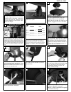
12
Lift canop
y to ceiling aligning the k
ey hole
slots with the screws on the bottom of
the mounting bracket. Rotate the canopy
counter clockwise to lock in place.
Tighten the screws to secure the canop
y
.
See inset for keyhole shape
13
A
ttach blade br
ackets to blades using
the blade bracket screws and wash-
ers provided.
14
Check the motor for plastic shipping sta-
bilizer tabs and remove if they are pres-
ent. The screws, w
ashers and motor pads
are pre-installed to the blade holders.
Attach blade assembly to motor and
tighten screws securely.
15
C
onnect black and blue wire from fan to Black or (Hot)
wire from house. Connect White wire from Fan to
White (Neutral) wire from house. Connect Ground
l
eads from mounting bracket and downrod to Ground
lead from house.
Refer to Safety Tips section of
manual.
11
House
Fan
Blue
Black
White
Green
Black
White
Ground
Loosen 2 screws and remove 1
screw. Save screw removed.
16
Twist lower cover plate into place by
twisting in direction of arrow.
R
eplace 1 screw removed and tighten
all 3 screws securely.
18
R
emove screws as shown and save.
17
F
or Canadian installation and for USA fan and
l
ight kit combinations over 35 lbs, in both flush
and downrod mode the safety cable must be
installed into the house structure beams using
the 3” lag screws,washers, and lock washers.
provided. Make sure that when the safety cable
is fully extended the leadwires are longer than
the cable and no stress is placed on the lead-
wires.
10
Safety cable installation
Safety Cable
L
ag Screw
s
afety
cable
3
” lag
screw
l
ock
washer
w
asher


Find Your Products By Category
Please Login
