
0
Owner's of the Sea Gull Lighting Fan Sea Gull Lighting Fan gave it a score of 0 out of 5. Here's how the scores stacked up:
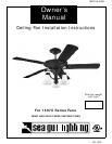
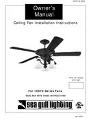
15070-UL-ENG
HC-1274
Installation work and electrical wiring must be done by qualified person(s) in accordance with applicable codes and standards (ANSI/NFPA 70-
1999), including fire-rated construction.
U
se this unit only in the manner intended by the manufacurer. If you have any questions contact the manufacturer.
After making the wire connections, the wires should be spread apart with the grounded conductor and the equipment-grounding conductor on one
side of the outlet box and ungrounded conductor on the other side of the outlet box.
Before you begin installing the fan, Switch power off at Service panel and lock service disconnecting means to prevent power from being switched
on accidentally. When the service disconnecting means cannot be locked, securely fasten a prominent warning device, such as a tag, to the service
panel.
Be cautious! read all instructions and safety information before installing your new fan. Review the accompanying assembly diagrams.
W
hen cutting or drilling into wall or ceiling, do not damage electrical wiring and other hidden utilities.
Make sure the installation site you choose allows the fan blades to rotate without any obstructions. Allow a minimum clearance of 7 feet from the
floor to the trailing edge of the blade.
To reduce the risk of fire, electric shock, or personal injury, mount to outlet box or supporting system acceptable for fan support.
(Mounting must support at least 35 lbs.)
Do not bend blade holders during installation to motor, balancing or during cleaning. Do not insert foreign object between rotating blades.
Attach the mounting bracket using only the hardware supplied with the outlet box.
To reduce the risk of fire or electric shock, do not use this fan with any solid state fan speed control device, or variable speed control.
If this unit is to be installed over a tub or shower, it must be marked as appropriate for the application.
NEVER place a switch where it can be reached from a tub or shower.
The combustion airflow needed for safe operation of fuel-burning equipment may be affected by this unit’s operation. Follow the heating equipment
manufacturer’s guideline safety standards such as those published by the National Fire Protection Association (NFPA), and the American Society for
Heating, Refrigeration and Air Conditioning Engineers (ASHRAE) and the local code authorities.
Before servicing or cleaning unit, Switch power off at Service panel and lock service disconnecting means to prevent power from being switched on
accidentally. When the service disconnecting means cannot be locked, securely fasten a prominent warning device, such as a tag, to the service
panel.
1.
2.
3.
4.
5
.
6.
7.
8.
9.
10.
1
1.
12.
13.
14.
15.
Installation
W
ARNING: TO REDUCE THE RISK OF FIRE, ELECTRIC SHOCK, OR INJURY TO PERSONS,
OBSERVE THE FOLLOWING: READ AND SAVE THESE INSTRUCTIONS
SA
FETY
TI
PS
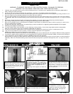
TTOOOOLLSS RREEQQUUIIRREEDD
PPhhiilllliippss SSccrreewwddrriivveerr WWiirree CCuutttteerrss PPlliieerrss SStteepp LLaaddddeerr
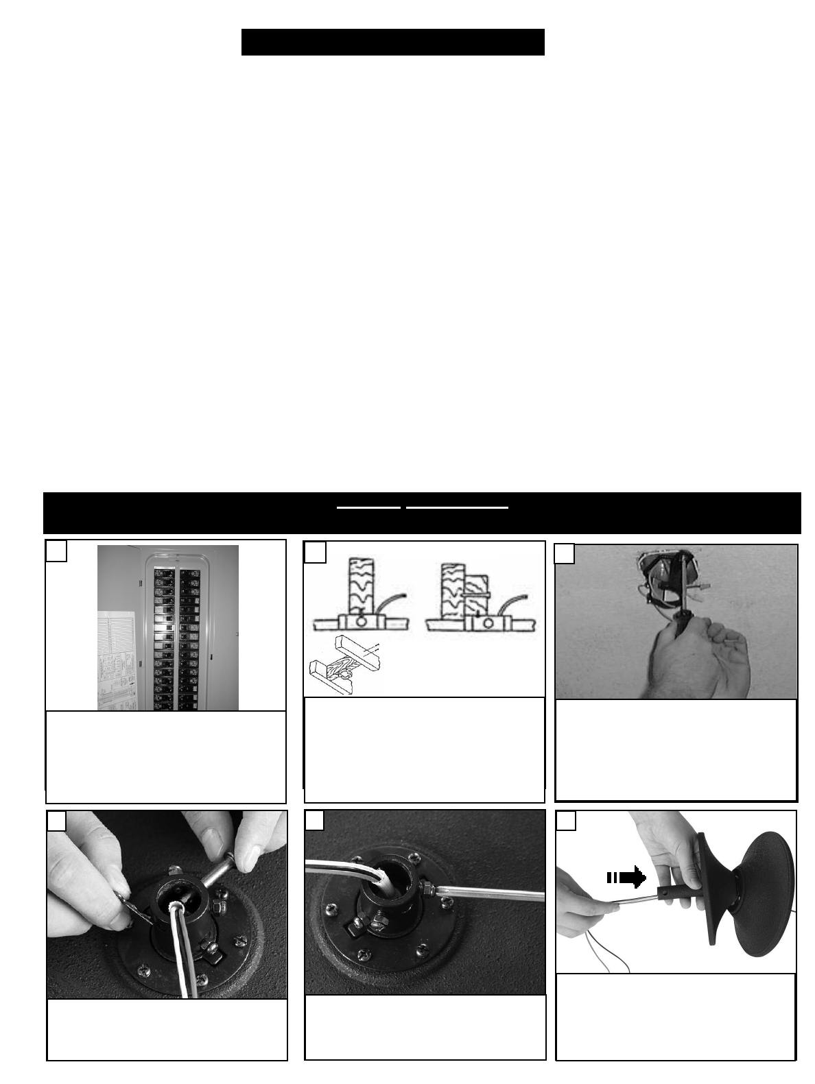
Before y
ou begin installing the fan, Switch
power off at Service panel and lock service dis-
connecting means to prevent power from being
switched on accidentally. When the service dis-
connecting means cannot be locked, securely
fasten a prominent warning device, such as a
tag, to the service panel.
Before installing this fan make sure
the outlet bo
x is properly installed to
the house structure. To reduce the
risk of fire, electric shock, or person
-
al injury, mount to outlet bo
x or sup
-
porting system acceptable for fan
support.
(Mounting must support at least 35
lbs.)
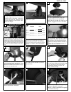
2
1
OUTLET BOX METHOD
Use metal outlet box suitable for fan support
(must support 35 lbs). Before attaching fan to
outlet box, ensure the outlet box is securely
fastened by at least two points to a structural
ceiling member ( a loose box will cause the fan
to wobble).
Use only the screws provided
with the outlet box.
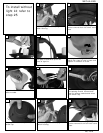
3
Place canopy and then yoke cover
over downrod as shown. Then
thread the lead wires and safety
cable from the fan through the
downrod as shown.
6
R
emo
v
e k
eeper from pin. Pull pin out
and replace k
eeper
, sa
v
e for later.
4
Loosen the 2 set screws and nuts till
you can not feel them on inside of
yoke.
5


Find Your Products By Category
Please Login
