
0
Owner's of the Craftmade Outdoor Ceiling Fan MOR54ESP3, MOR54MWW3 gave it a score of 0 out of 5. Here's how the scores stacked up:
page 4
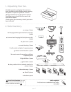
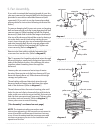
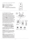
5. Fan Assembly.
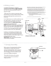
If you wish to extend the hanging length of your fan,
you must remove the hanging ball from the downrod
provided to use with an extended downrod (sold
separately). [If you wish to use the downrod provided,
please proceed to instructions following the dotted line
below.]
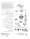
To remove hanging ball, loosen set screw on hanging
ball and remove pin and clip. Lower hanging ball and
remove stop pin. Slide hanging ball off the original
downrod, A, and slide it down the longer downrod, B
(the top of the downrod should be noted as having a
set screw hole; use this hole when setting the set
screw). Insert stop pin into top of extended downrod
and raise hanging ball. Be sure stop pin aligns with
slots on the inside of the hanging ball. Tighten set
screw securely. [Refer to diagram 1.]
Remove vice from safety cable by loosening the
screw and nut on the vice. [Refer to diagram 2.]
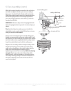
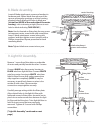
Tip: To prepare for threading electrical wires through
downrod, apply a small piece of electrical tape to the
ends of the electrical wires--this will keep the wires
together when threading them through the
downrod.
Loosen yoke set screws and nut at top of motor
housing. Remove pin and clip from downrod (if you
have not already done so). Slide downrod through
canopy and yoke cover.
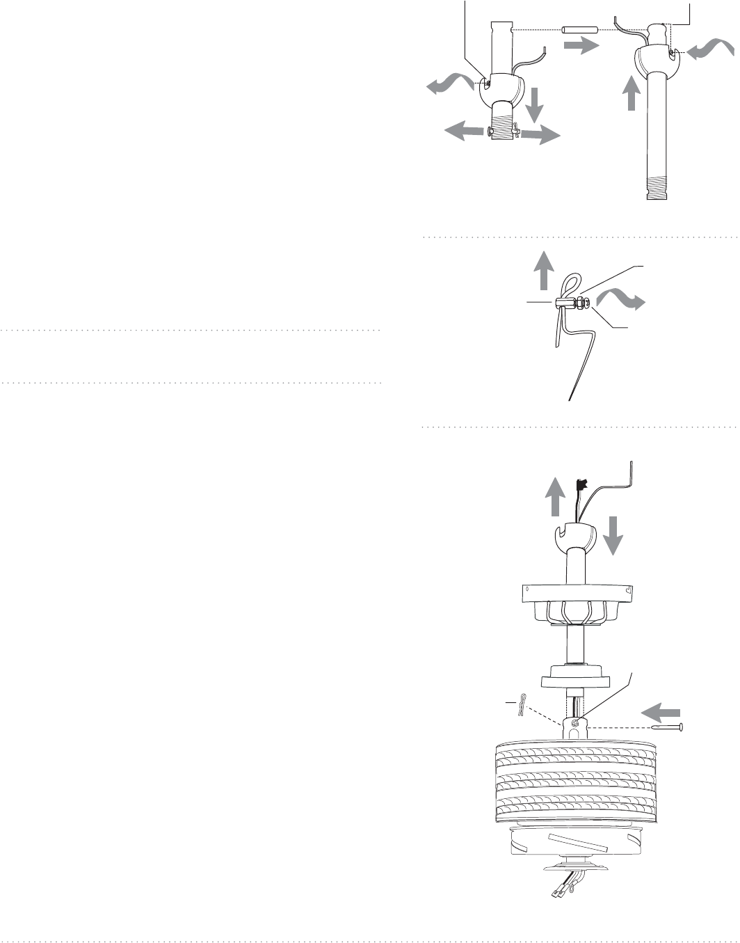
Thread safety cable and electrical wires through
downrod and pull extra wire slack from the upper
end of the downrod. [Refer to diagram 3.]
Thread downrod into the motor housing yoke until
holes for pin and clip in downrod align with holes in
yoke--make sure wires do not get twisted. Re-insert pin
and clip that were previously removed. Tighten yoke
set screws and nut securely. [Refer to diagram 3.]
Lower yoke cover to motor housing.
["Fan Assembly" continued on next page.]
vice
diagram 2
nut
screw
NOTE: The important safety precautions and
instructions appearing in the manual are not meant to
cover all possible conditions and situations that may
occur. It must be understood that common sense and
caution are necessary factors in the installation and
operation of this fan.
safety cable
diagram 1
pin
clip
set screw hole
set screw
hanging ball
stop pin
A
B
diagram 3
safety cable
yoke cover
canopy
downrod
electrical wiring
pin
clip
motor
housing
yoke set screw


Find Your Products By Category
Please Login
